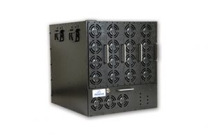
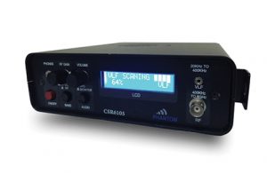
GENERAL DESCRIPTION
150W total Output Power
The RSJ470 is responsive jammer which designed for blocking RF based initiation of RCIEDs.
The system is comprised of two main RF blocks:
- An SDR – Software Defined Radio block receiver.
- A DDS Based Jammer.
During normal operation, the system “listens” to the predefined spectrum and collects the RF atmosphere in the protected band. The collected data is analyzed in real time and full flow and its output contains the frequency measurement, the signal’s characteristics and the RF signal level.
Once any signal inside the protected band is classified by the system as a threat, the jammer takes action and transmits a white-noise signal that jams the communication between the receiver and the transmitter.
This transmission lasts for several milliseconds and then returns to reception mode, continuing to monitor the designated spectrum.
- The user defines the threshold level for receiving signals to be jammed.
- Scanning time is fast enough to jam DTMF based initiated RCIEDs.
- The minimum channel step is 10 KHz and the maximum step is 1MHz.
- The user can also define the number of channels to be monitored and to be jammed whenever the RF energy level is greater than the set threshold.
- The IF bandwidth can be selected between 15 KHz to 2MHz based on a digital filter.
- AM & FM demodulators are integrated part of the system and can be used for real-time listening purposes.
SPECIAL FEATURES
- Batteries – 2 hours continuous operation, between charges\
- Distance between Tx & Rx – more than 150m
- Response time ~ 10 ms
- Adjustable Jamming cycle- between 100 ms to 10 seconds
REMOTE CONTROL UNIT (RCU)
Includes a Ruggedized Touchpad as based Remote Control Unit is installed next to driver.
The RCU has the following functions:
- System calibration of jamming bands
- On/off
- BIT
- Touch screen
- Communication connection with the system
TECHNICAL SPECIFICATIONS
RF Characteristics
| Max. Output Power per Band | 30W |
| Min. Output Power per Band | 1W |
| Output Power Control Steps | 1dB |
| Internal Modulation | FM Hopping Frequency/Responsive |
| Signal Source | DDS & PLL synthesized |
| Power Supply | Li Po Battery, 25.9V/24AH |
| Antenna | External – Omni-Directional Antenna outputs includes VSWR protector |
| Jammed Frequency Band | VHF/UHF |
| Channel Band Width | 15KHz – 2MHz |
| Minimum Channel Spacing | 10KHz |
Physical Data
| Dimensions | Pelican 1610 |
| Weight | 15 Kg with battery |
Environment of Operation
| Operating Temp | -10ºC – +65ºC |
| Humidity | 5% – 80% |
Optional Accessories
| Rechargeable Battery | 25.9V/24AH |
| Control Cable Via PC | LAN |
RECEIVER BLOCK
RF Characteristics
| Frequency Range | 20-520 MHz |
| Frequency Setting | 10 KHz, 25 KHz, 100 KHz, 1 MHz |
| Sensitivity , Overall Noise Figure | -132dBm, typ. 10 dB |
| Demodulation | AM, FM, CW |
| IF Bandwidth | 15 KHz – 2MHz |
| Squelch | Can be set between -132dBm to -30dBm |
| Sensitivity , Overall Noise Figure | -132dBm, typ. 10 dB |
Scan Characteristics
| Automatic Memory Scan | 4000 Channels |
| Frequency Scan | Start/Stop/Step definition with receiving data set |
Inputs/Outputs
| Scan Characteristics | Scan Characteristics |
| Digital IF output | Parallel / Serial Data up to 512 kbps: 16 bit |
Environment of operation
| Operating Temp | -30 – +65° C |
| Humidity | 5 – 80% |
| Storage Temp. | -40°C – +70°C |
Power
| Operating Voltage, Current | 11.1V, 500mA |
*Specifications are subject to change without prior notice
Ver. 1.00.09.17


